Source notes and corrections
Normal operating pressure is 6.5–7.5 PSI, confirmed by ISKYPOOL. Component references follow the original diagrams: the valve inlet facing the pump is E (Figures 07–09), and the air release knob is 13 (Figure 01). The startup operation is labelled RINSE, consistently with step 2 and the valve-function table. These editorial corrections do not alter the original PDF or its images.
The X-filled contacts in the original are placeholders, not service contacts. For ISKYPOOL support: info@iskypool.com.
ISKYPOOL correction: normal operating pressure is 6.5–7.5 PSI. This correction replaces the conflicting pressure entry in the source. The attached original PDF and page images are retained unchanged.
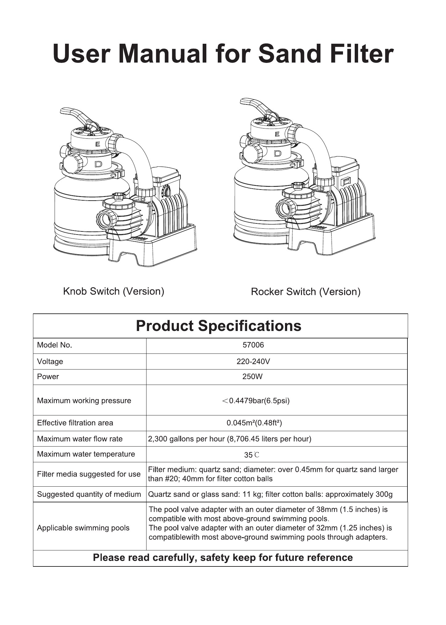
User Manual for Sand Filter
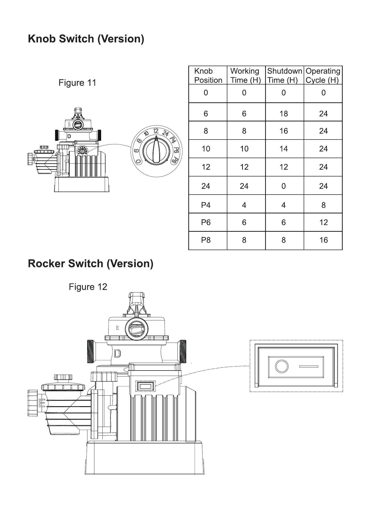
Knob Switch (Version)
Rocker Switch (Version)
Product Specifications:
| Model No. | 57006 |
| Voltage | 220-240V |
| Power | 250W |
| Normal operating pressure | 6.5–7.5 PSI |
| Effective filtration area | 0.045m²(0.48ft²) |
| Maximum water flow rate | 2,300 gallons per hour (8,706.45 liters per hour) |
| Maximum water temperature | 35℃. |
| Filter media suggested for use | Filter medium: quartz sand; diameter: over 0.45mm for quartz sand larger than #20; 40mm for filter cotton balls |
| Suggested quantity of medium | Quartz sand or glass sand: 11 kg; filter cotton balls: approximately 300g |
| Applicable swimming pools | The pool valve adapter with an outer diameter of 38mm (1.5 inches) is compatible with most above-ground swimming pools. The pool valve adapter with an outer diameter of 32mm (1.25 inches) is compatiblewith most above-ground swimming pools through adapters. |
Please read carefully, safety keep for future reference
Safety Instructions
The following essential safety precautions shall always be followed when you are installing or using this electrical equipment:
Warning: To minimize the risk of injury, do not allow children to use this product. Children and persons without capacity for civil conduct shall be closely supervised at all times.
Warning: Keep children away from this product and its power cords.
Warning: Close supervision is essential to prevent children from playing with this product.
Warning: This appliance is not designed for use by individuals (including children) with reduced physical, sensory or mental capabilities, or those with insufficient skills and intellectual disabilities, unless their safety is ensured by a guardian who provides both protection and necessary supervision and guidance.
Warning: Position the product away from the pool to prevent children from climbing on it toaccess the pool.
Warning: Risk of electric shock. Connect this product only to a grounding-type receptacle protected by a ground-fault circuit interrupter (GFCI). If uncertain, engage a qualified electrician for proper installation. The receptacle should have the maximum ground fault current not exceeding 30mA. Do not use portable socket-outlets.
Warning: Always unplug this product from the outlet before removal, cleaning, servicing ormaking any adjustments.
Warning: Do not bury the power cord in soil. Place the power cord in a safe location to avoid damage from lawn mowers and other equipment.
Warning: If the power cord is damaged, do not operate this product.
Warning: To minimize the risk of electric shock, do not connect extension cords, timers, plug adapters or converter plugs to the filter unit. A permanent electrical outlet shall be provided.
Warning: Do not connect or disconnect this product while standing in water or with wet hands.
Warning: After installation, the plug should be accessible and visible to the user.
Warning: Do not operate this product while the pool is in use.
Warning: Installation and removal shall be performed by adults only.
Warning: This product is designed exclusively for portable pools. Do not use with permanently installed pools. A storable pool can be readily disassembled for storage and reassembled using its original components.
Warning: To prevent product damage and injury, always switch off the product before adjusting the control valve position.
Warning: To minimize the suction entrapment risk, never enter the pool if the filter cover is loose, damaged, broken or missing. Replace the filter cover immediately if any of these conditions are found.
Warning: Never play or swim near the filter cover. Your hair or body may become trapped, causing permanent injury or drowning.
Warning: Do not operate this product if the pressure gauge reading of the unit exceeds the maximum rated pressure.
Warning: Hazardous pressure. Improper tank cover assembly could make the cover blow off, resulting in severe injury, property damage or death.
Cautions:
Use this product only for the purposes described in the manual.
Adhere to all safety requirements and recommenda
Important Safety Instructions: Read and Follow All Safety Instructions
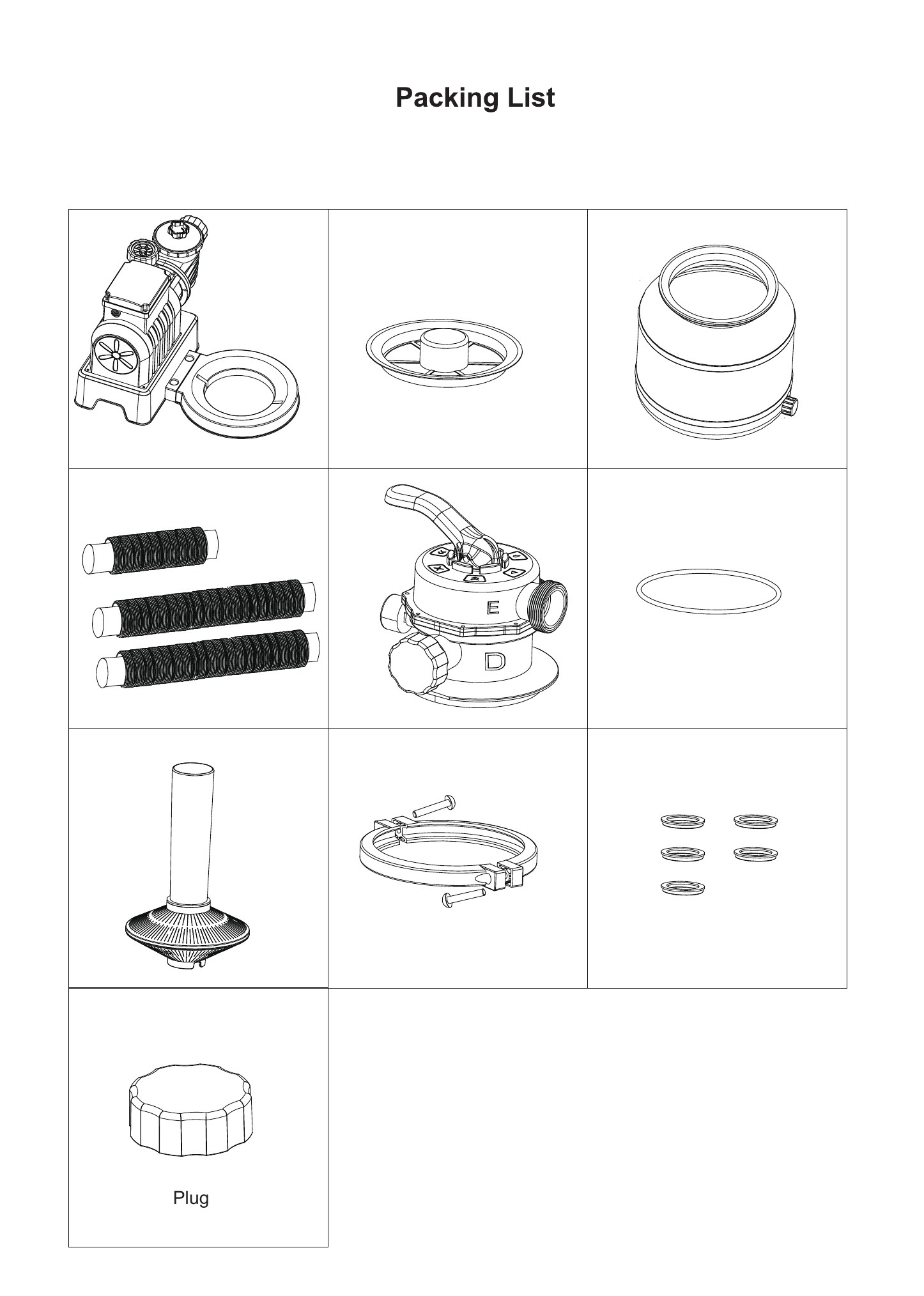
Packing List
Plug
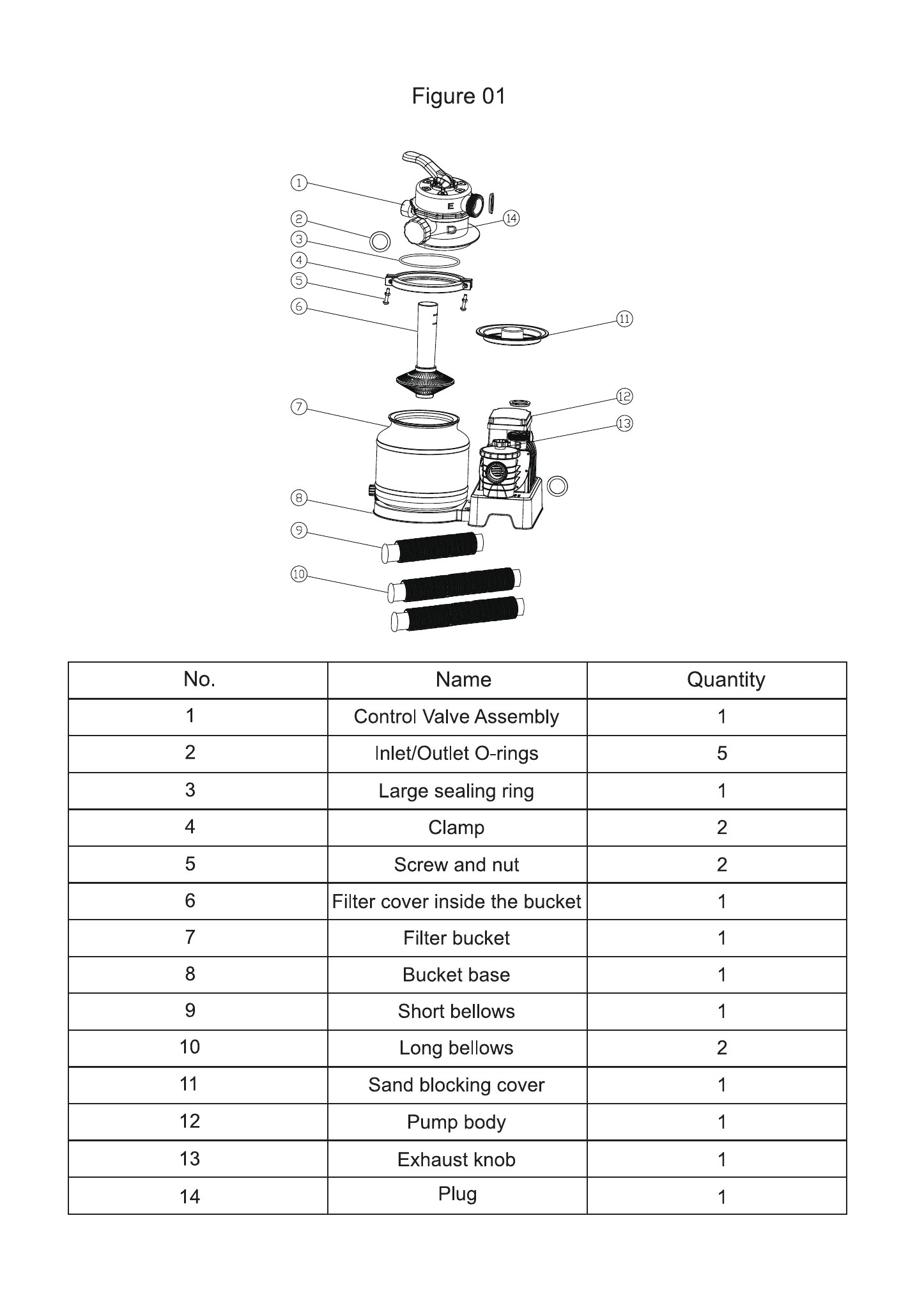
Figure 01
| No. | Name | Quantity |
|---|---|---|
| 1 | Control Valve Assembly | 1 |
| 2 | Inlet/Outlet O-rings | 5 |
| 3 | Large sealing ring | 1 |
| 4 | Clamp | 2 |
| 5 | Screw and nut | 2 |
| 6 | Filter cover inside the bucket | 1 |
| 7 | Filter bucket | 1 |
| 8 | Bucket base | 1 |
| 9 | Short bellows | 1 |
| 10 | Long bellows | 2 |
| 11 | Sand blocking cover | 1 |
| 12 | Pump body | 1 |
| 13 | Exhaust knob | 1 |
| 14 | Plug | 1 |
Preparation before installation
Required tool: 1 Phillips screwdriver
Product installation location and assembly:
- The product shall be installed on a firm and level ground.
- Adequate access, space and lighting shall be provided for daily maintenance.
- The motor requires ventilation and cooling. Do not place this product in damp or poorly ventilated areas.
Installation instructions:
Place the product in the location you have chosen.
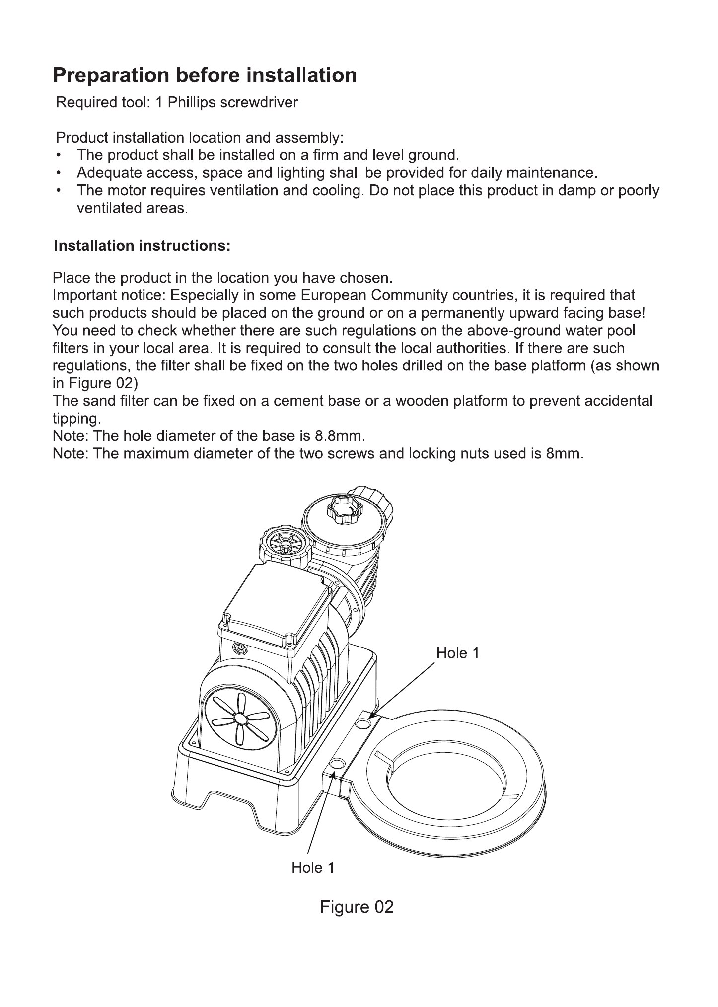
Important notice: Especially in some European Community countries, it is required that such products should be placed on the ground or on a permanently upward facing base! You need to check whether there are such regulations on the above-ground water pool filters in your local area. It is required to consult the local authorities. If there are such regulations, the filter shall be fixed on the two holes drilled on the base platform (as shown in Figure 02)
The sand filter can be fixed on a cement base or a wooden platform to prevent accidental tipping.
Note: The hole diameter of the base is 8.8mm.
Note: The maximum diameter of the two screws and locking nuts used is 8mm.
Figure 02
Hole 1
Hole 1
Sand loading:
Note: #20 quartz sand or glass sand. The particle size is within the range of 0.45-0.85 millimeters (0.018-0.033 inches), and the overall particle uniformity coefficient is less than 1.75.
Step 1:
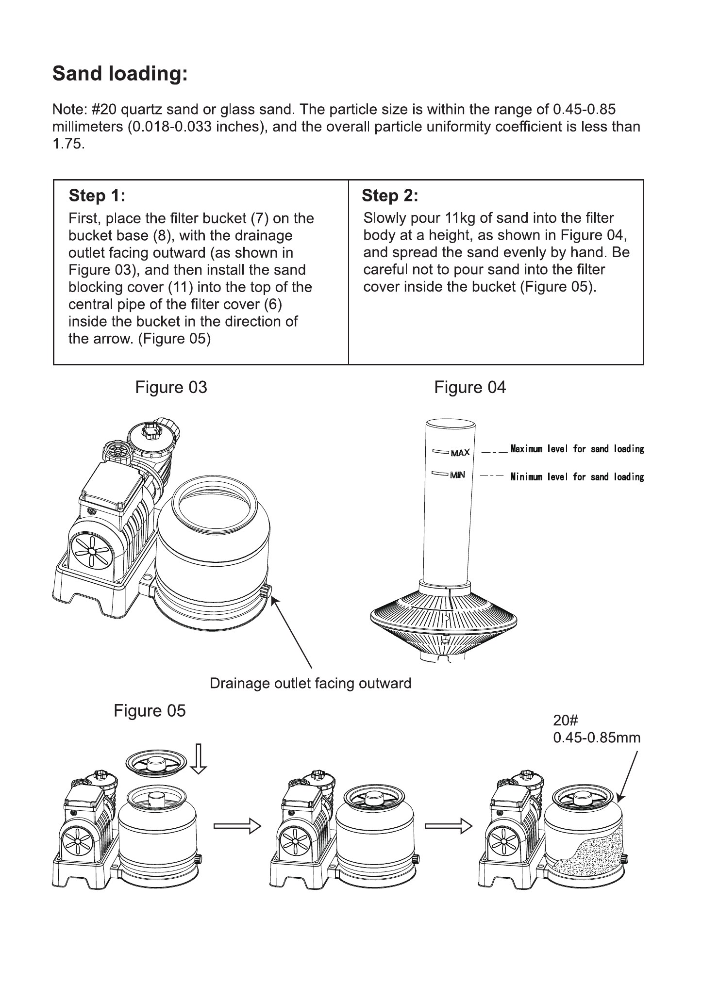
First, place the filter bucket (7) on the bucket base (8), with the drainage outlet facing outward (as shown in Figure 03), and then install the sand blocking cover (11) into the top of the central pipe of the filter cover (6) inside the bucket in the direction of the arrow. (Figure 05)
Step 2:
Slowly pour 11kg of sand into the filter body at a height, as shown in Figure 04, and spread the sand evenly by hand. Be careful not to pour sand into the filter cover inside the bucket (Figure 05).
Figure 03
Figure 04
MAX—Maximum level for sand loading
MIN—Minimum level for sand loading
Drainage outlet facing outward
Figure 05
20# 0.45-0.85mm
Installation of filter bucket:
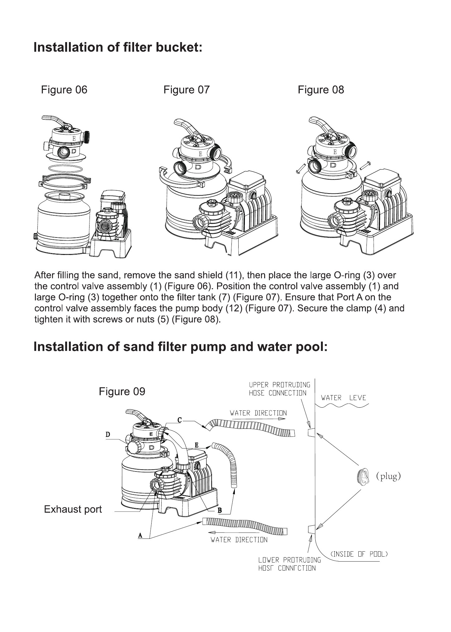
Figure 06
Figure 07
Figure 08
After filling the sand, remove the sand shield (11), then place the large O-ring (3) over the control valve assembly (1) (Figure 06). Position the control valve assembly (1) and large O-ring (3) together onto the filter tank (7) (Figure 07). Ensure that Port E on the control valve assembly faces the pump body (12) (Figure 07). Secure the clamp (4) and tighten it with screws or nuts (5) (Figure 08).
Installation of sand filter pump and water pool:
Figure 09
UPPER PROTRUDING HOSE CONNECTION
WATER LEVE
WATER DIRECTION
WATER DIRECTION
(plug)
(INSIDE OF POOL)
LOWER PROTRUDING HOST CONNECTION
Exhaust port
A B C D E
Installation Steps:
- Install the inlet/outlet O-rings (2) onto ports E, B, C, D and A.
- Attach and secure the long corrugated hose (10) between the lower pool fitting and inlet A as illustrated in (Fig. 09).
- Attach and secure the short corrugated hose (9) between outlet B and inlet E as illustrated in (Fig. 09).
- Attach and secure the long corrugated hose (10) to outlet D as illustrated in (Fig. 09), with the other end being positioned on the ground for drainage.
- Remove the plug from the inlet and outlet joint of the water tank.
Control Valve Operation
Warning: Risk of electric shock. Connect this product only to a grounding-type receptacle protected by a ground-fault circuit interrupter (GFCI). If uncertain, engage a qualified electrician for proper installation. The receptacle should have the maximum ground fault current not exceeding 30mA. Do not use portable socket-outlets.
Warning: To minimize the risk of electric shock, do not connect extension cords, timers, plug adapters or converter plugs to the filter unit. A permanent electrical outlet shall be provided.
Warning: Do not connect or disconnect this product while standing in water or with wet hands.
Warning: Do not operate this product if the pressure gauge reading of the unit exceeds the maximum rated pressure.
Warning: Before operating, verify all corrugated hoses are connected and secured, and the filter contains the appropriate amount of sand.
Warning: Before operating, ensure that the product is connected to a grounding-type receptacle protected by a ground-fault circuit interrupter (GFCI).
Warning: The control valve has a closed position. Do not operate the product when the control valve is closed.
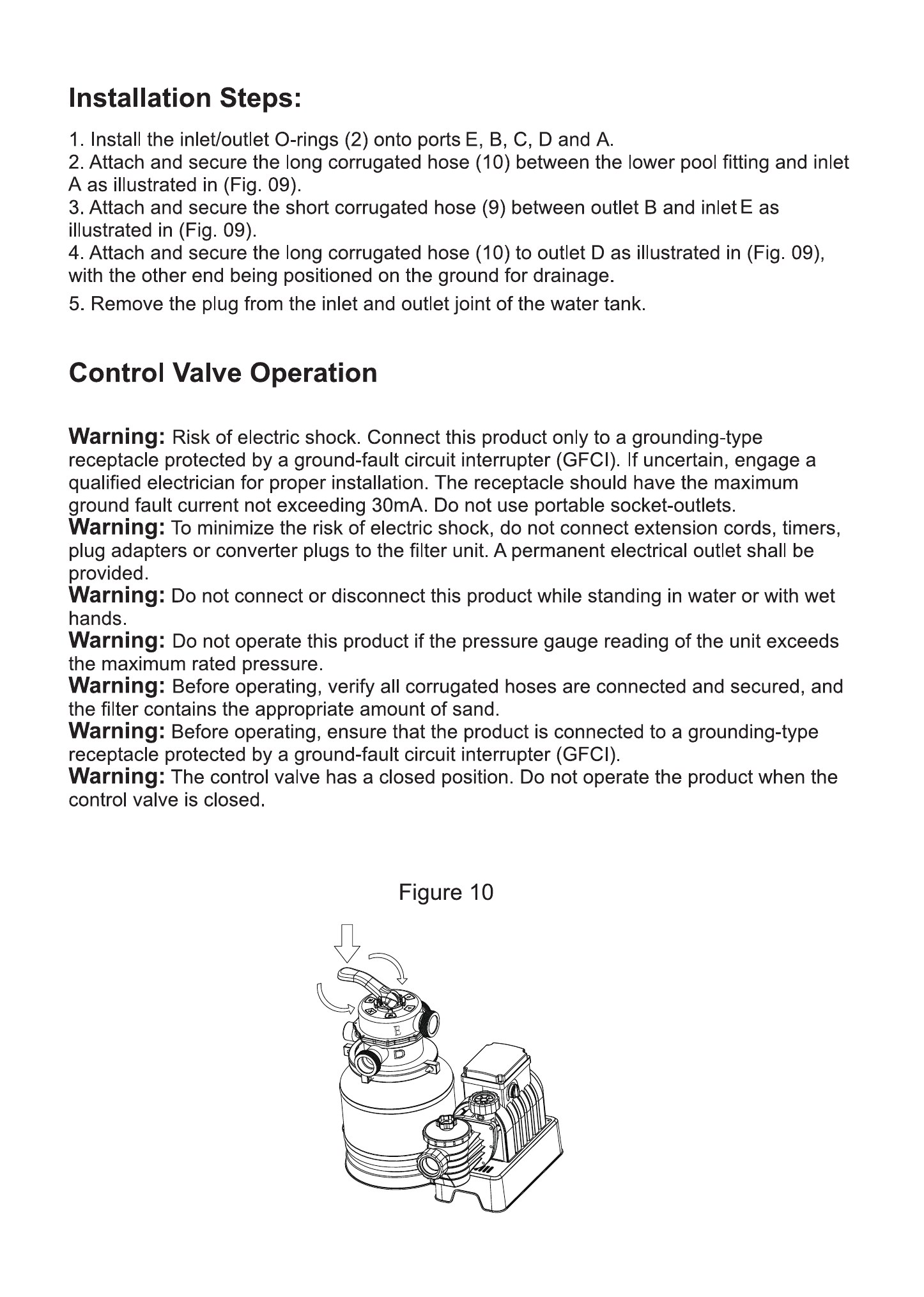
Figure 10
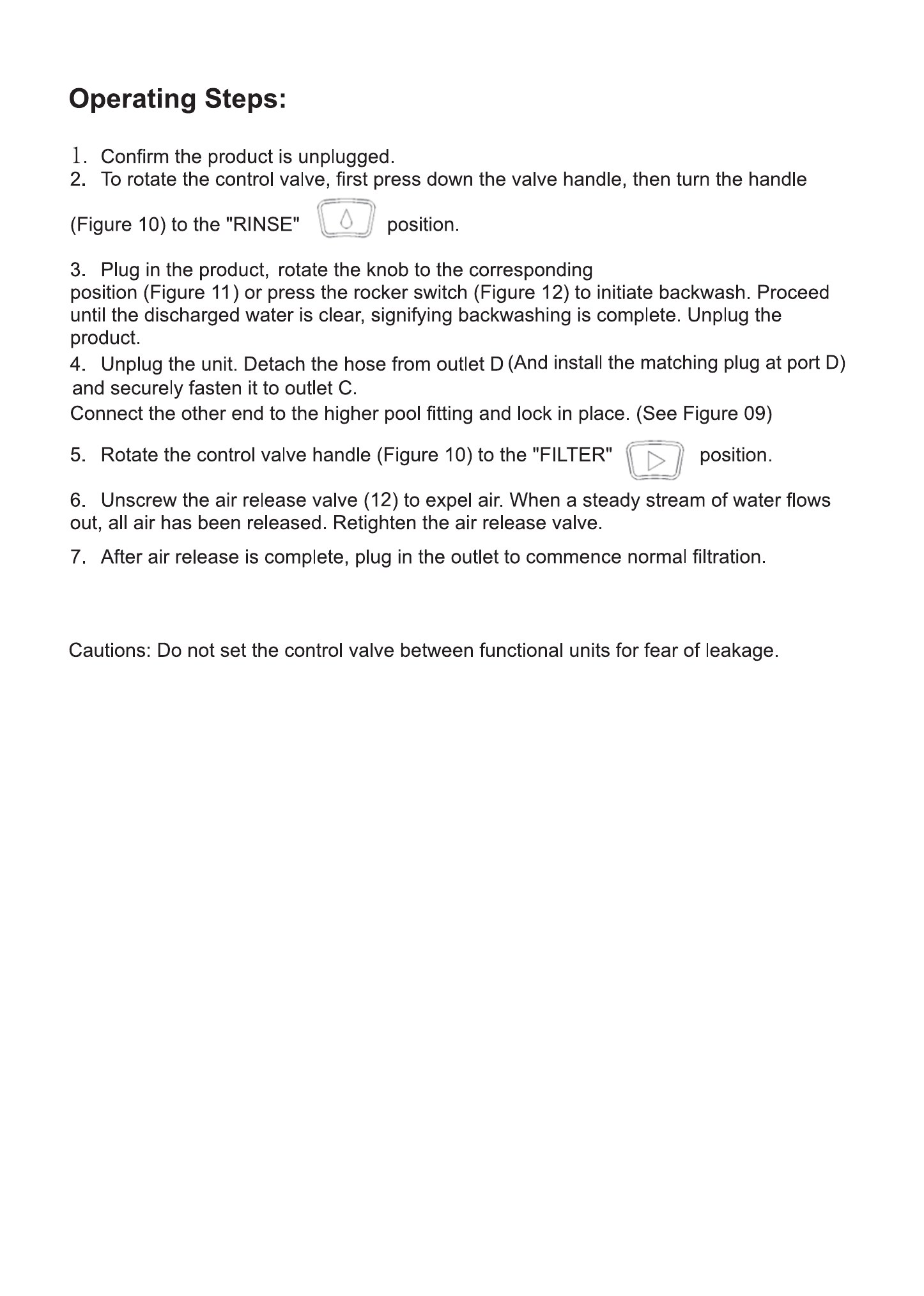
Operating Steps:
- Confirm the product is unplugged.
- To rotate the control valve, first press down the valve handle, then turn the handle (Figure 10) to the "RINSE" [droplet icon] position.
- Plug in the product and rotate the knob to the corresponding position (Figure 11), or press the rocker switch (Figure 12), to start the RINSE operation selected in the preceding step. Continue until the discharged water is clear, then unplug the product.
- Unplug the unit. Detach the hose from outlet D (And install the matching plug at port D) and securely fasten it to outlet C.
Connect the other end to the higher pool fitting and lock in place. (See Figure 09) - Rotate the control valve handle (Figure 10) to the "FILTER" [right triangle icon] position.
- Unscrew the air release valve (13) to expel air. When a steady stream of water flows out, all air has been released. Retighten the air release valve.
- After air release is complete, plug in the outlet to commence normal filtration.
Cautions: Do not set the control valve between functional units for fear of leakage.
Knob Switch (Version)
Figure 11
| Knob Position | Working Time (H) | Shutdown Time (H) | Operating Cycle (H) |
|---|---|---|---|
| 0 | 0 | 0 | 0 |
| 6 | 6 | 18 | 24 |
| 8 | 8 | 16 | 24 |
| 10 | 10 | 14 | 24 |
| 12 | 12 | 12 | 24 |
| 24 | 24 | 0 | 24 |
| P4 | 4 | 4 | 8 |
| P6 | 6 | 6 | 12 |
| P8 | 8 | 8 | 16 |
Rocker Switch (Version)
Figure 12
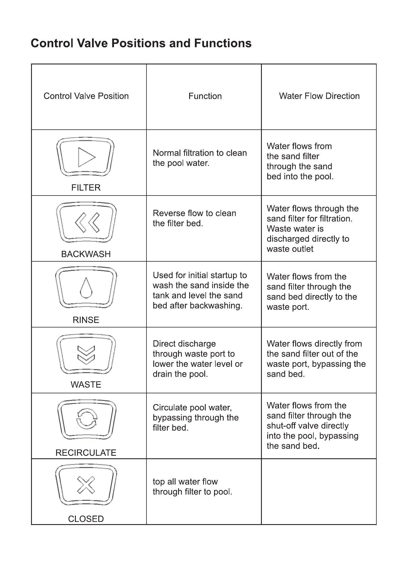
Control Valve Positions and Functions
| Control Valve Position | Function | Water Flow Direction |
|---|---|---|
| FILTER | Normal filtration to clean the pool water. | Water flows from the sand filter through the sand bed into the pool. |
| BACKWASH | Reverse flow to clean the filter bed. | Water flows through the sand filter for filtration. Waste water is discharged directly to waste outlet |
| RINSE | Used for initial startup to wash the sand inside the tank and level the sand bed after backwashing. | Water flows from the sand filter through the sand bed directly to the waste port. |
| WASTE | Direct discharge through waste port to lower the water level or drain the pool. | Water flows directly from the sand filter out of the waste port, bypassing the sand bed. |
| RECIRCULATE | Circulate pool water, bypassing through the filter bed. | Water flows from the sand filter through the shut-off valve directly into the pool, bypassing the sand bed. |
| CLOSED | top all water flow through filter to pool. |
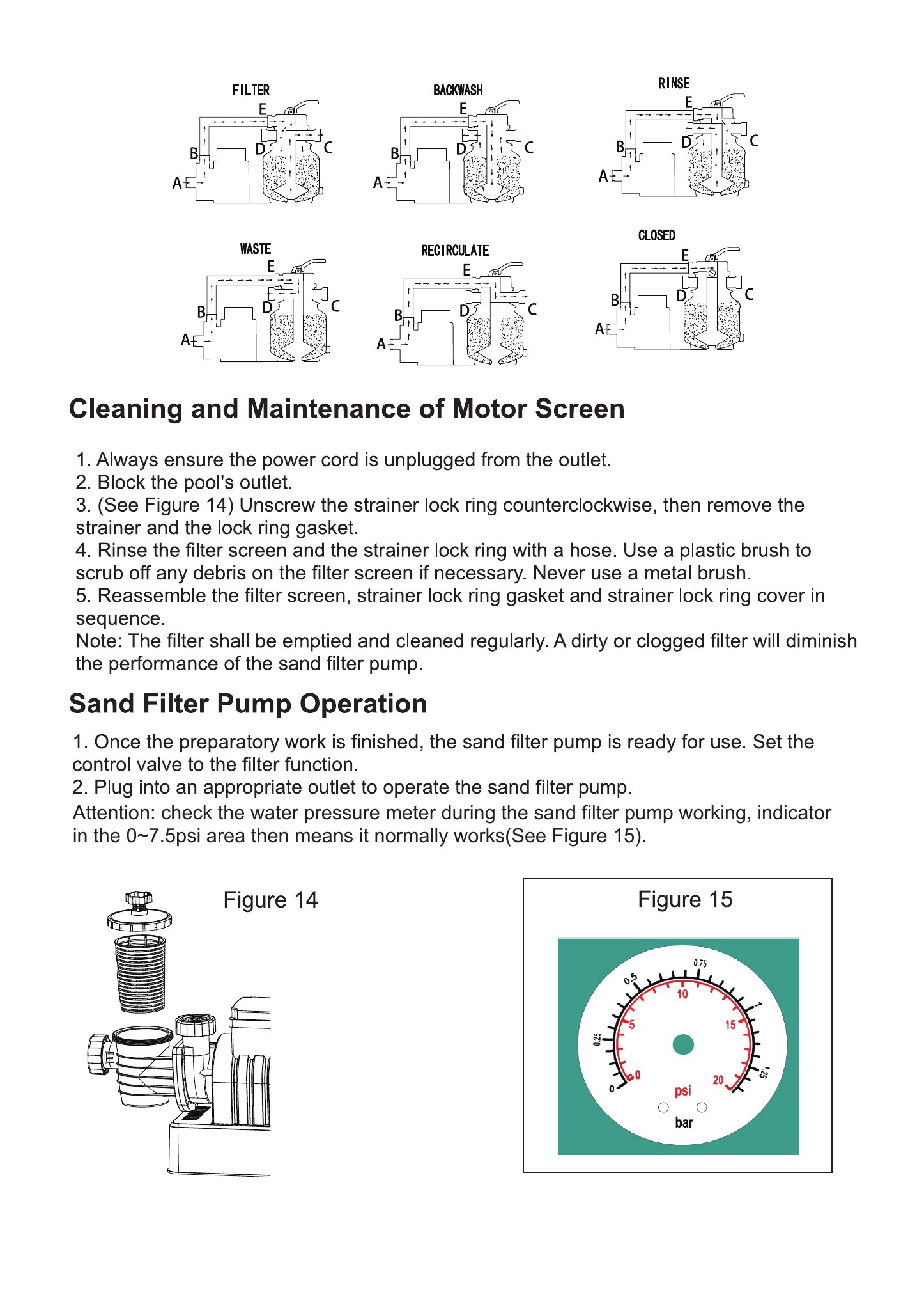
FILTER
BACKWASH
RINSE
WASTE
RECIRCULATE
CLOSED
Cleaning and Maintenance of Motor Screen
- Always ensure the power cord is unplugged from the outlet.
- Block the pool's outlet.
- (See Figure 14) Unscrew the strainer lock ring counterclockwise, then remove the strainer and the lock ring gasket.
- Rinse the filter screen and the strainer lock ring with a hose. Use a plastic brush to scrub off any debris on the filter screen if necessary. Never use a metal brush.
- Reassemble the filter screen, strainer lock ring gasket and strainer lock ring cover in sequence.
Note: The filter shall be emptied and cleaned regularly. A dirty or clogged filter will diminish the performance of the sand filter pump.
Sand Filter Pump Operation
- Once the preparatory work is finished, the sand filter pump is ready for use. Set the control valve to the filter function.
- Plug into an appropriate outlet to operate the sand filter pump.
Attention: check the water pressure gauge while the sand filter pump is operating. The normal operating range is 6.5–7.5 PSI (see Figure 15).
Figure 14
Figure 15
Attention:
You must make ensure the power supply of sand filter pump plug off first then can process maintain, otherwise, it maybe happen serious risk like human body hurt or dead.
Attention:
Please clean the sand bed or renewal sand when pressure meter indicator point to 7.5~9.0psi area. Need utilize “Reverse flow washing” and “Washing” function.
Attention:
We advise you monthly one time clean or fix time clean according to use.
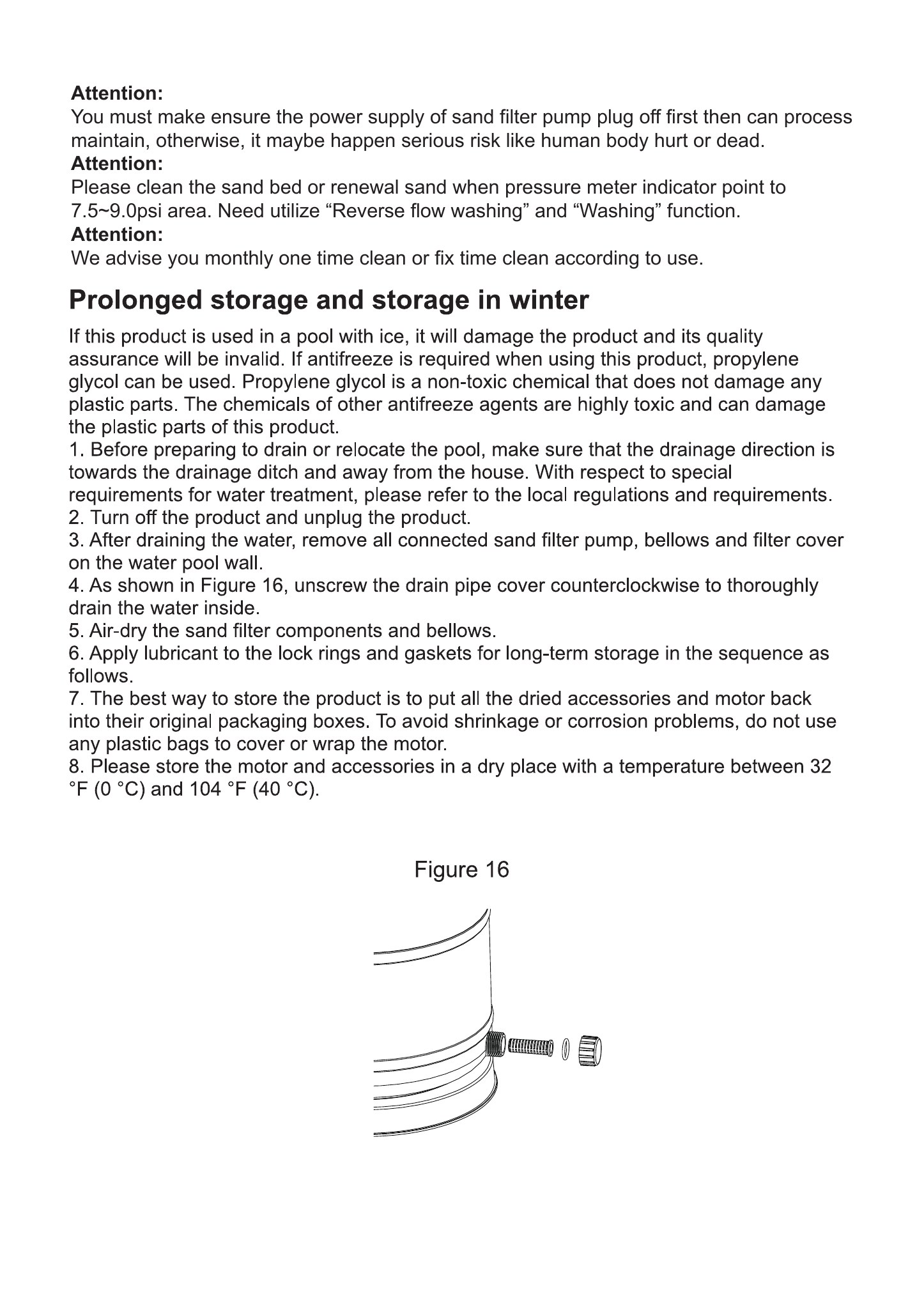
Prolonged storage and storage in winter
If this product is used in a pool with ice, it will damage the product and its quality assurance will be invalid. If antifreeze is required when using this product, propylene glycol can be used. Propylene glycol is a non-toxic chemical that does not damage any plastic parts. The chemicals of other antifreeze agents are highly toxic and can damage the plastic parts of this product.
- Before preparing to drain or relocate the pool, make sure that the drainage direction is towards the drainage ditch and away from the house. With respect to special requirements for water treatment, please refer to the local regulations and requirements.
- Turn off the product and unplug the product.
- After draining the water, remove all connected sand filter pump, bellows and filter cover on the water pool wall.
- As shown in Figure 16, unscrew the drain pipe cover counterclockwise to thoroughly drain the water inside.
- Air-dry the sand filter components and bellows.
- Apply lubricant to the lock rings and gaskets for long-term storage in the sequence as follows.
- The best way to store the product is to put all the dried accessories and motor back into their original packaging boxes. To avoid shrinkage or corrosion problems, do not use any plastic bags to cover or wrap the motor.
- Please store the motor and accessories in a dry place with a temperature between 32 °F (0 °C) and 104 °F (40 °C).
Figure 16
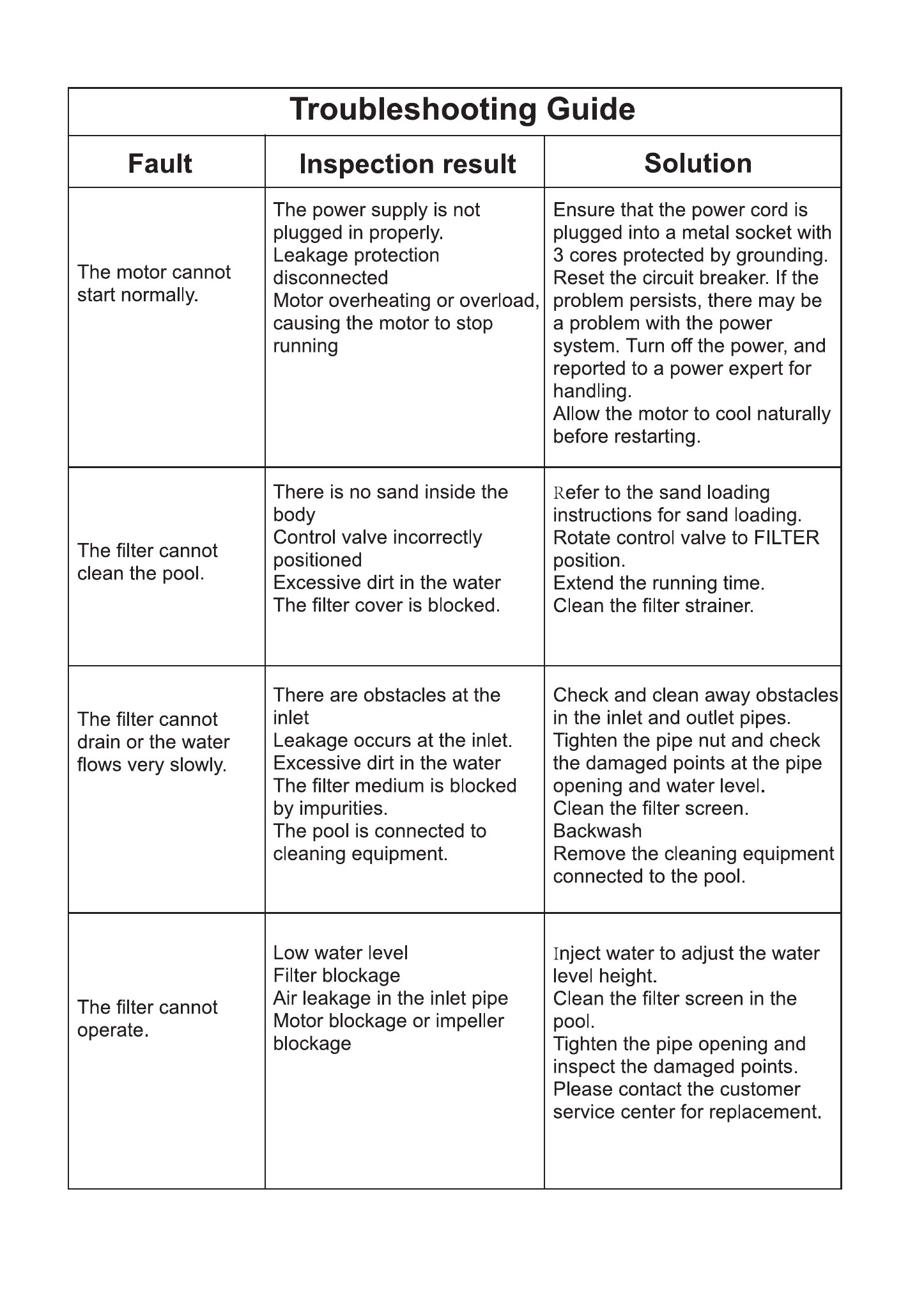
Troubleshooting Guide
| Fault | Inspection result | Solution |
|---|---|---|
| The motor cannot start normally. | The power supply is not plugged in properly. Leakage protection disconnected Motor overheating or overload, causing the motor to stop running | Ensure that the power cord is plugged into a metal socket with 3 cores protected by grounding. Reset the circuit breaker. If the problem persists, there may be a problem with the power system. Turn off the power, and reported to a power expert for handling. Allow the motor to cool naturally before restarting. |
| The filter cannot clean the pool. | There is no sand inside the body Control valve incorrectly positioned Excessive dirt in the water The filter cover is blocked. | Refer to the sand loading instructions for sand loading. Rotate control valve to FILTER position. Extend the running time. Clean the filter strainer. |
| The filter cannot drain or the water flows very slowly. | There are obstacles at the inlet Leakage occurs at the inlet. Excessive dirt in the water The filter medium is blocked by impurities. The pool is connected to cleaning equipment. | Check and clean away obstacles in the inlet and outlet pipes. Tighten the pipe nut and check the damaged points at the pipe opening and water level. Clean the filter screen. Backwash Remove the cleaning equipment connected to the pool. |
| The filter cannot operate. | Low water level Filter blockage Air leakage in the inlet pipe Motor blockage or impeller blockage | Inject water to adjust the water level height. Clean the filter screen in the pool. Tighten the pipe opening and inspect the damaged points. Please contact the customer service center for replacement. |
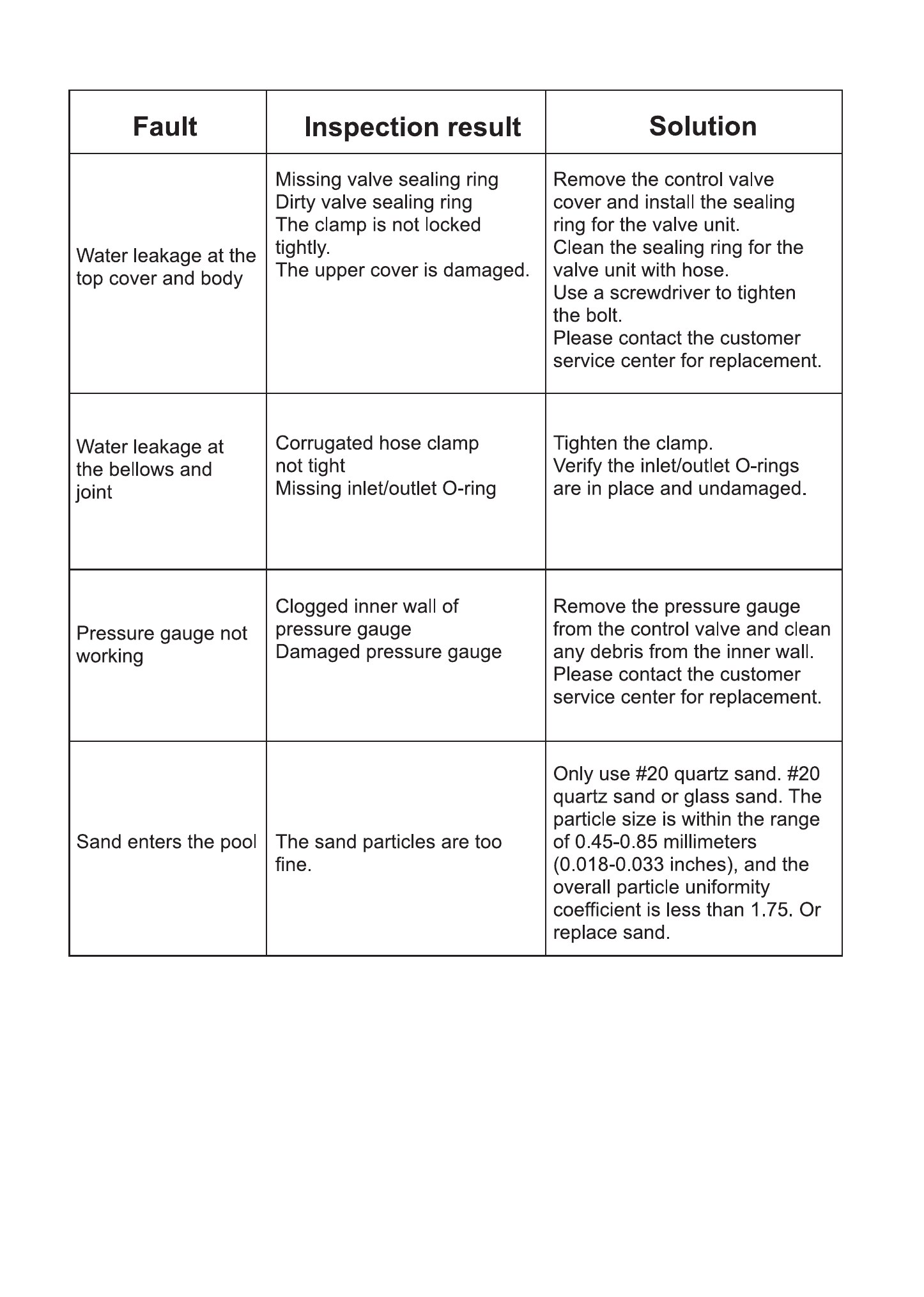
| Water leakage at the top cover and body | Missing valve sealing ring Dirty valve sealing ring The clamp is not locked tightly. The upper cover is damaged. | Remove the control valve cover and install the sealing ring for the valve unit. Clean the sealing ring for the valve unit with hose. Use a screwdriver to tighten the bolt. Please contact the customer service center for replacement. |
| Water leakage at the bellows and joint | Corrugated hose clamp not tight Missing inlet/outlet O-ring | Tighten the clamp. Verify the inlet/outlet O-rings are in place and undamaged. |
| Pressure gauge not working | Clogged inner wall of pressure gauge Damaged pressure gauge | Remove the pressure gauge from the control valve and clean any debris from the inner wall. Please contact the customer service center for replacement. |
| Sand enters the pool | The sand particles are too fine. | Only use #20 quartz sand. #20 quartz sand or glass sand. The particle size is within the range of 0.45-0.85 millimeters (0.018-0.033 inches), and the overall particle uniformity coefficient is less than 1.75. Or replace sand. |
SWITZERLAND
XXXXXXXXXXX
XXXXXXXXX
XXXXXXX
XXXXXX
Tel: XXXXXXX
E-mail: XXXX@XXXXXXXXX
GERMANY
XXXXXXXXXXX
XXXXXXXXX
XXXXXXX
XXXXXX
Phone: XXXXXXXXXX
Email: XXXXXX@XXXXXXXX
(In case of doubt on the pump or any circulation devices, contact a qualified installer, or the manufacturer/importer/distributor; the address or telephone number where the consumer/installer can obtain additional information during the installation in the event of problems.)
Original document
Original manufacturer PDF (English) ↗Original language: English